This Article explains how to set up your Polyga Rotary Table. Using a rotary table streamlines the scanning process. Only minimal user interaction is required to achieve a 360° scan of a static object.
Setting Up the Hardware
To set up the hardware:
- Ensure FlexScan3D has been installed, including the rotary driver component (installed by default).
- Connect the cable from the table motor to one of the available ports on the controller box.
- Plug in the power cable for the controller box.
- Connect the USB cable between the controller box and the PC.
Before the rotary table can be used in FlexScan3D, it must be calibrated.
Calibrating the Rotary Table
Once the rotary is calibrated, FlexScan3D will automatically align meshes based on the rotary position. To calibrate the rotary, you will first need to make sure you already have a scanner connected and open. For HDI Advance, the scanner must also be calibrated.
To calibrate the rotary table:
- Create a new project or open an existing one.
- On the Project tab, click the Scan button (top-left of the application window) to switch to Scan mode.
Note that a valid calibration must be open and the scanner connected. Otherwise, this button will be disabled. - Click the Enable Rotary checkbox.
The software will attempt to connect to the rotary. If it succeeds, you will immediately be prompted to calibrate. If it does not succeed, please make sure all cables are connected properly to the controller box and PC, and also ensure that the power cord is plugged in. - Place a calibration board on the rotary, ensuring that it can be seen by the camera(s) and that it is not overexposed or underexposed.
For HDI Advance scanners, the calibration board must be the exact same size as the one used during calibration of the scanner. Otherwise, alignment will not work properly.
For HDI 120 scanners, use a 10 mm calibration board. For HDI 109 scanners, use a 5 mm calibration board. - Click OK to start this calibration process.
The rotary will rotate as needed and capture images of the calibration board at various angles. A message will be displayed informing you whether or not the calibration was successful.
360° Scanning
The most common use for a rotary is to achieve a complete 360° scan of an object. If the rotary is not yet calibrated, first follow the steps for calibrating the rotary table.
To do a 360° scan of an object:
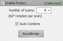
- If the Enable Rotary checkbox is not checked, check it now.
- Choose the number of desired scans.
More scans will result in better coverage, but setting this value too high may result in a lot of excess data, which will slow down scanning and mesh operations. We recommend doing 6 to 12 scans. - Choose whether or not to automatically combine the scans by checking/unchecking the Auto Combine checkbox.
Automatically combining the scans will simplify subsequent operations on the mesh, but may not be desired in all cases. (For example, if the scans are intended to be exported for alignment in third-party mesh processing software.) - Make sure the object is on the rotary table facing the scanner, and then click Scan.
Scanning, processing, and alignment may take several minutes to complete. - Often, you will also need to place the object on its side and run another scan to capture the bottom and top of the object. Align to the other scans as needed.
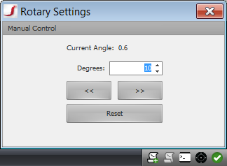
Manual Jogging
The rotary can also be used manually. Click the rotary icon to bring up the rotary controls. If the rotary is calibrated, new scans will get aligned based on the rotary position.
This is a video tutorial on how to calibrate a rotary table: